Resistors in Series and Parallel Explained
Almost every circuit has resistors connected in series, in parallel, or both. Knowing how they combine lets you find the total resistance, the current and the voltage at any point. This guide covers the rules, with examples. The series and parallel resistor calculators do the sums.
Resistors in series
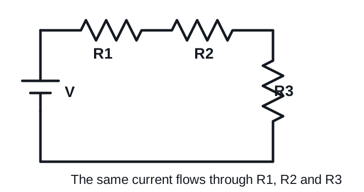
Resistors are in series when they are connected end to end with nothing branching off between them. There is only one path for the current.
Rtotal = R1 + R2 + R3 + …
- The current is the same through every resistor.
- The voltage is shared, in proportion to each resistance.
- The total is always larger than the largest resistor.
Example: 220 Ω + 330 Ω + 470 Ω = 1,020 Ω.
Resistors in parallel
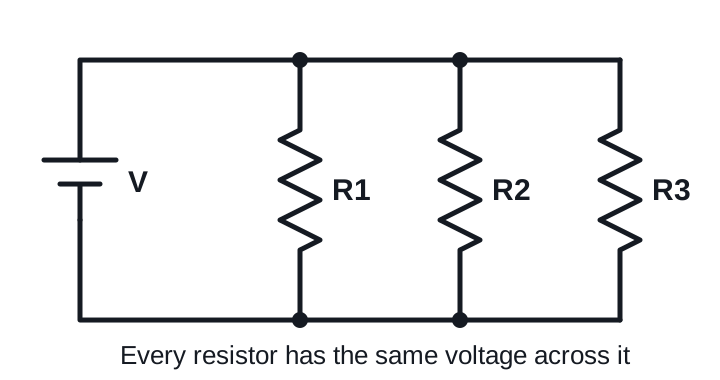
Resistors are in parallel when both ends of each are connected to the same two points.
1 / Rtotal = 1 / R1 + 1 / R2 + 1 / R3 + …
For two resistors: Rtotal = (R1 × R2) / (R1 + R2).
- The voltage is the same across every resistor.
- The current is shared, with the most going through the smallest resistor.
- The total is always smaller than the smallest resistor.
Example: 220 Ω in parallel with 330 Ω = 72,600 / 550 = 132 Ω.
Quick comparison
| Series | Parallel | |
|---|---|---|
| Total resistance | Sum of all | Less than the smallest |
| Current | Same through each | Splits between them |
| Voltage | Splits between them | Same across each |
| If one fails open | Everything stops | The others carry on |
Mixed series-parallel circuits
Real circuits often combine both. Simplify them one step at a time, starting from the part furthest from the supply:
- Find a group that is clearly in series or clearly in parallel.
- Replace it with a single equivalent resistor.
- Redraw the circuit and repeat until only one resistor is left.
Example
R1 = 100 Ω is in series with a parallel pair, R2 = 300 Ω and R3 = 600 Ω, on a 12 V supply.
- R2 parallel R3 = (300 × 600) / 900 = 200 Ω.
- Add R1 in series: 100 + 200 = 300 Ω total.
- Total current: 12 / 300 = 40 mA.
- Working back: R1 drops 0.04 × 100 = 4 V, leaving 8 V across the parallel pair.
- R2 carries 8 / 300 = 26.7 mA and R3 carries 8 / 600 = 13.3 mA, which add up to 40 mA.
The voltage drop calculator can check step 4 if you enter 100 Ω and 200 Ω as the series string.
How to spot series and parallel on a board
Look at the nodes, the points where wires join. Two resistors are in parallel only if both of their ends share nodes. They are in series only if they share one node and nothing else connects to it. Resistors that share one node with a third branch leaving it are neither. They form part of a larger network and need Kirchhoff’s laws to solve.
Practical uses
- Making odd values: 2 × 4.7 kΩ in series is 9.4 kΩ, and 2 × 4.7 kΩ in parallel is 2.35 kΩ. See standard resistor values for what you can buy.
- Sharing heat: several resistors together can handle more power than one. See resistor power ratings explained.
- Dividing voltage: two resistors in series make a voltage divider.