Choosing Pull-Up Resistor Values
A digital input with nothing connected to it does not read reliably as high or low. It “floats”, picking up noise and flipping state at random. A pull-up resistor fixes this by gently holding the input at a known level until something else pulls it the other way. This guide explains how to choose the value.
How a pull-up works
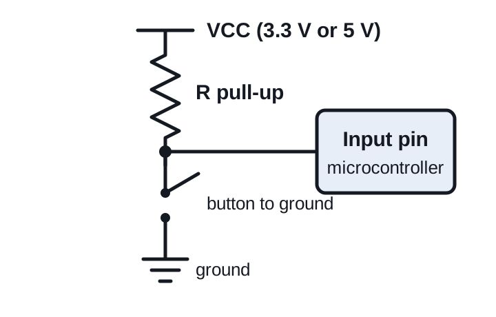
The resistor connects the input pin to the supply (VCC). With the button open, almost no current flows into the high-impedance input, so the pin sits at close to VCC and reads high. Press the button and the pin connects straight to ground, so it reads low. The resistor stops that from becoming a short circuit, and only a small current flows:
I = VCC / R
A pull-down resistor is the mirror image: it connects the pin to ground, and the button connects it to VCC.
The trade-off
- Too low a value wastes current every time the input is pulled low. A 100 Ω pull-up on 5 V draws 50 mA when the button is pressed, which is a lot for a battery device.
- Too high a value makes a weak pull-up. Leakage currents and noise can drag the voltage down, and the pin charges slowly through the resistor and any capacitance on the line, giving slow, rounded edges.
For most buttons and switches, anything from about 4.7 kΩ to 10 kΩ sits comfortably in the middle. At 5 V, 10 kΩ draws just 0.5 mA when pressed (check with the Ohm’s law calculator).
Internal pull-ups
Most microcontrollers have pull-up resistors built in that you can switch on in software, for example pinMode(pin, INPUT_PULLUP) on Arduino. They are typically 20 kΩ to 50 kΩ on classic AVR chips such as the ATmega328P, and of a similar order on many other families. They are fine for buttons on short wires. For long cables, noisy environments or fast signals, add an external resistor of a lower value.
I2C pull-ups
I2C lines are open-drain: devices can pull them low but never drive them high. The pull-up resistors do that, and their value sets how fast the lines rise.
- Minimum value: the resistor must not let more current flow than the devices can sink when pulling low, which is 3 mA in standard and fast mode. Rmin = (VCC − 0.4 V) / 3 mA, so about 970 Ω at 3.3 V and 1.53 kΩ at 5 V.
- Maximum value: set by the bus capacitance and the required rise time. Long wires and many devices add capacitance and need lower values.
In practice, 4.7 kΩ is the usual starting point for 100 kHz on a short bus, and 2.2 kΩ is common at 400 kHz. Check that only one set of pull-ups is fitted: many sensor breakout boards include their own, and several boards in parallel can bring the effective value too low. Work out the combined value with the parallel resistor calculator.
Open-drain and open-collector outputs
Interrupt lines, some sensors and comparators have open-drain outputs that need a pull-up to produce a high level. The same trade-off applies: 4.7 kΩ to 10 kΩ for slow signals, lower for faster ones. Check the maximum sink current of the output in its datasheet.
Quick reference
| Use | Typical value |
|---|---|
| Push button or switch, short wires | 10 kΩ (or the internal pull-up) |
| Button on a long cable | 1 kΩ to 4.7 kΩ |
| I2C, 100 kHz | 4.7 kΩ |
| I2C, 400 kHz | 2.2 kΩ |
| Reset pins, enable pins | 10 kΩ |
| Open-drain interrupt lines | 4.7 kΩ to 10 kΩ |
These are starting points, not rules. Datasheets for specific chips often recommend a value, and that should take priority.